| Model Number |
Width (mm) |
Thinckness (mm) |
Speed |
| SLHR-1000 |
1000 |
2.0-6.0 |
80-120 MPM |
| SLHR-1600 |
1600 |
2.0-6.0 |
80-120 MPM |
| SLHR-2000 |
2000 |
2.0-11.0 |
50-120 MPM |
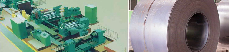
Line Composition
- Coil car
- Uncoiler
- Pinch Roll leveler
- Guiding (peer to peer)device
- Slitting machine
- Waste Selvage device (scrap reels device)
- Recoiler with Pusher Plate & Over Arm Separator
- Coil Car
- Electrical Panels & hydraulics.
|
Working Process
HR coil is loaded on the Coil Car by overhead crane. The coil car travels on rail lines by AC motor & brings the coil to the uncoiler. The lifting cylinder of the coil car centralizes the coil to the Uncoiler centre. The two opposed bodies of the uncoiler are mover towards each other so that the cones of both the bodies enter the ID of the coil to hold the coil firmly. The coil car is lowered and taken back.
The uncoiler drive rotates the coil and brings the leading end in the feeding position. Snubber roll in lowered on the coil and the coil straps are cut. With the operation of peeler table & uncoiler drive, the leading end is fed in the Pinch Roll leveler. The rolls are pressed and the drives of uncoiler & pinch roll take the leading end forward though shear. The end is cut if required. The leading end is further moved through vertical guides in to the slitter. As the slitter motor accepts the leading end, the pinch roll & snubber rolls are taken up and uncoiler drive is disengaged.
Slitter takes the strip further but now in slitted condition. All the slits are taken forward over the roller table in to the Recoiler drum where the ends are inserted in the gripping slot. The ends are properly positioned in the slot as per the setting of Over Arm Separator and the drum is expanded.
The slitter and recoiler drives are inched forward together and a couple of turns are loosely wound over the drum. The line is put in RUN mode. The recoiler tightens the turns against the resistance of the slitter and the winding goes on. As the coil builds up on the recoiler drum, the line speed goes up and reaches the maximum when the coil is finished. The over arm separator keeps moving up with the built up by a special hydraulic valve maintaining a set pressure on the coil.
The line goes on until the coil is completely wound over the recoiler drum. The trailing ends are clamped over the slit coils and overarm separator is lifted. The exit coil car is brought below the coil and lifted to support the coil weight. The drum is collapsed and the pusher plate is operated along with the coil car to take the coil smoothly out of the drum.
The slitted coils are removed by the overhead crane and the line is ready for the next coil.
|